Wooden Cart Wheels
Article by Robert Ducat-Brown
I have built three street organs to John Smith’s designs, starting with the Busker, the Universal and then the 65 key MIDI organ Topsy.   These got progressively better in sound - probably because of the increased number of notes - and maybe because I got a bit better at it.   Having said that, I have a firm favourite one, and that is the 26 note Universal.  
There was however something missing from my Universal, and that was a cart.   It was normally played on a small table, and transported on a trolley with three-inch swivel casters.    I needed to make a cart for it.

Having checked out many examples amongst my collection of photographs taken at organ  events, and looking on line, I decided that I would really like my cart to have spoked wooden wheels, although I had no idea how to make them.   I checked the Internet, and the nearest help I found was building a spinning wheel.   Only the basic idea was of use to me, as a cart wheel is quite different in style and size - however the mode of production seemed to suit.    I reckoned  that the wheels would need to be about 91/2" diameter, which I thought I could turn on my metalwork lathe - although only 31/2" centre height, I could turn something larger in the gap at the headstock end.   The plans for the spinning wheel had six spokes, but I required eight to give mine sufficient strength.   My rims were to be made in eight sections with a hole drilled in each for the spokes.

To start, I decided to do a test run for turning the rims, by making a prototype out of 1/2" ply.   I have an angle cutting saw which is set out in various degrees.   I needed to cut the end of rim section at 221/2 degrees - my saw cut at 22.3, but I thought that would be close enough.   I cut the sections, glued them together, and mounted them on a wooden backing board attached to the lathe  faceplate.  I could only fit 91/8" in the lathe but I intended to fit rubber tyres of some sort which would bring the diameter up to nearly 91/2".  

I had a supply of quite large pieces of oak which I intended to use.   I cut this on a bench saw to 17/16" by 13/4" section - which allowed for the curve of the wheel rim.    Having planed this to size, I proceeded to cut the 32 rim pieces - and a few spares - on the angle  cutting saw.   l then drilled a 1/2" hole in the centre of each section of the wheel rim on what would be the inside edge.   The spinning wheel article showed the sections of the wheel fixed together by a tongue and groove joint.   I did not think that I needed to go to that trouble, so l made 1/8" slots in the ends on the wheel
rim sections with a router and made some 1/8" slithers of matching wood to form a strong joint when fitted in the slots with the grain following that of the rims.    The eight sections of each wheel were then glued together and clamped in position with a cord tourniquet.

I set everything up to turn the rims in the lathe, just as I had done with the prototype.   PROBLEM!   With the face plate, wooden backing board and wheel rim, the whole thing was too wide to fit in the gap of my lathe.   At the suggestion of a friend. I decided to use my small milling machine, with the wheel rims set up on a rotating table.   This arrangement is probably best shown in Fig 1. 

The table is rotated by a small hand turned wheel at the front.   It is turned against the rotating mill cutter so that small amounts of wood are being removed as it turns.  The rotating mill cutter stays in the same position.   If you were wanting to make some wheels like this and have a larger lathe than mine, I would suggest that the lathe would be far better for the job.

Turning the rims on the rotary table was slow, but in fact did a very good job. You may note in the photograph that I had an extractor set up - owing to the large amount of sawdust generated by the milling process.


The main problem was going to be getting the spokes into the wheel rim and the hub - because the rims were already glued together.  I believe that wheelwrights fix everything at one time and then hold it all together with a metal tyre which is shrunk on by heating and cooling.   Not something which I wanted to have a go at.

My plan was a hub as shown in Fig 2.   I do not have any pictures of the process, but I  did it all on the lathe using a dividing head for milling out the slots for the spokes. 


The next job was the spokes: I cut and planed the 32 spokes as a rectangular section about 4” long.   Each was placed in the lathe four jaw chuck and one end was turned to a good fit in the holes in the wheel rims - Fig 3.  
An example of some spokes and a wheel rim can be seen in Fig 4.
Where the spokes entered the wheel rim, a slight shaping was required to match the curve.

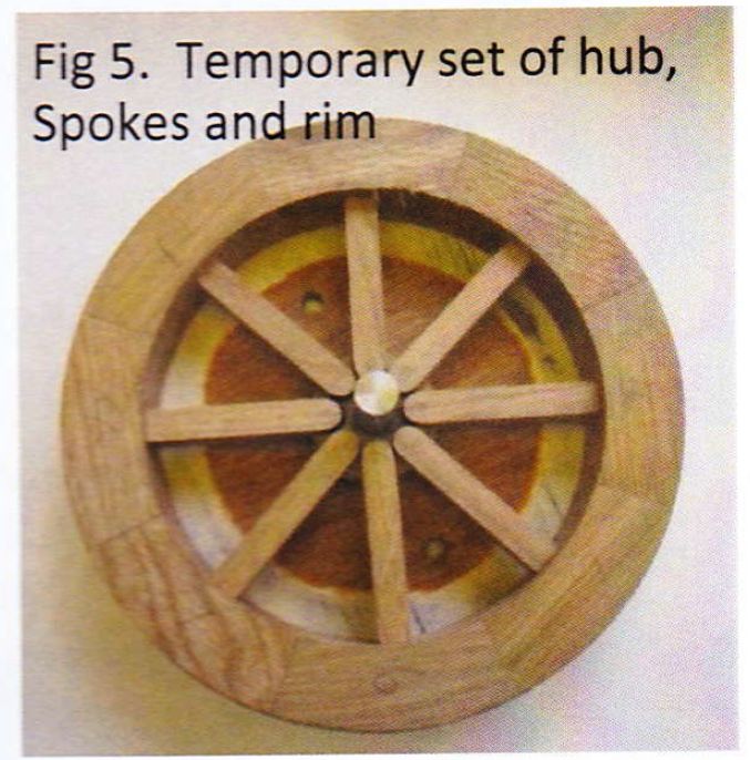
I then did a dummy set up to see how everything went together, which looked fine - Fig 5.

I did not want plain rectangular spokes, so I shaved them to an oval shape.   I have owned a couple of spoke shaves for about fifty years and although they have been used for many jobs, this was the first time that I had actually used them to shave spokes Fig 6. 

Everything went together very well - the other half of the hub fitted in place perfectly.   The centre axle hole was 5/8", and I fitted this with a bronze sleeve to allow for a 1/2" axle.   The wheels were sanded - Fig 7  - and then varnished to a satin finish.

The last job was to locate and fit rubber tyres. I thought this might be a problem to find, but the Internet soon produced a considerable number of suppliers of rubber strip and I was able to purchase just what I needed. This was 11/4” x 1/4" black rubber strip which I stuck to the rims of the wheels with Evostick adhesive - as recommended by the supplier.

Building the cart was quite a quick job compared to the wheels.

I had a supply of 1/2” Birch Ply which was easy to use.    I inset the bottom sides of the cart so that the wheels were level with the sides rather than sticking out.
At first I reused the wooden handle from my old trolley, but after noticing some rather ominous creeks and groans when I tilted the cart to turn a corner, I changed it to Aluminium.
The axles were made from some 5/8" steel rod which I had, with the ends turned down to fit in the 1/2" bushes in the wheels.   The end nuts were turned from some 1" hexagon brass which I found in my junk drawer - the ends were domed and threaded to suit the axles - Fig 8.
In fact, the only thing which I actually had to purchase was the rubber for the tyres and aluminium for the handle - so a very economical exercise.